Most books on electronics theory treat the subject of passives in the following way:
- A definition of voltage and current in ideal power supplies
- DC Theory, which provides definitions of resistors, capacitors and inductors and covers transients
- AC Theory, which covers the subject of complex math, impedance, and complex power
- All components are treated as ideal and abstract (literally just symbols on the page)
- The basics of circuit analysis
This always confused me because the theory was presented as AC and DC being completely separate. It seemed very concocted and not very realistic. I made it through college, by applying the AC/DC theory, but it wasn't until I started troubleshooting power circuits at my first engineering job that I really started to understand what capacitance, inductance and resistance really are and how they related to energy, power, voltage and current in a circuit.
When I began my first engineering job, most of the engineers around me seemed to know how a circuit would work just by looking at it. They would understand how different components interact with each other under steady-state and transient conditions. They would instinctively know how the little bits of inductance and capacitance were going to effect the circuit.
I, on the other hand, had no idea. I had a fledgling understanding of ideal components and whenever I tried to apply my AC/DC knowledge to these circuits it failed. It failed because it could not paint a complete picture of the circuit and could not accomplish what it was I was trying to achieve: designing a reliable circuit. What I needed was a circuit theory that I could apply in any situation to quickly understand how a circuit would respond under steady-state+transient conditions while taking in to account real components which all contain resistance, inductance, capacitance which all vary depending upon temperature, material, age, frequency, applied voltage, etc.
What I came up with is not a new theory, but just a new way of telling the same story. There are no new equations here, just a new way of presenting them. Instead of splitting capacitors and inductors from resistors, and AC theory from DC, I will instead present them all side while losing the AC/DC notation and instead teach steady-state and transient response. I will make cogent connections beteween real parts and their physical compositions (which for me was probably the most important step) and I will relate power and energy in general to electronics as a whole.
Energy, Work & Power
Physicists define energy as an intrinsic property of matter that enables work. In other words matter has the ability to act in some way, those ways are many and include physical, electrical, thermal, etc. Energy present in the universe can be moved from place to place over a period of time. Moving energy from one place to another is called work. Work performed over time is called power. So work describes the location characteristic of energy and power describes the time characteristic of energy. Note the two are not independent. Space and time are linked, nothing happens instantaneously.
For work that is constant, P=E/t
Fields & Types Of Energy
Physicists define fields as a physical phenomenon which acts over a volume or area, as forces on specific energy types. Gravitational forces act on mass. Electrical and magnetic fields act on charged particals (e.g. electrons). Both electrical and magnetic fields act directly on charged particles, but magnetic fields act more indirect.
Energy can be stored within matter (potential), or it can be in motion (kinetic). When a field acts on matter, it will convert some of the potential energy into kinetic energy. Just how much energy is displaced will depend on the device's intrinsic properties. As we shall see, in electromagnetics this will depend on it's resistance, capacitance and inductance.
Energy conversion takes place, for example, when electricity drives a motor. Energy conversion also takes place when you don't want it to, like when a CPU generates heat. If a CPU converted 100% of its electrical energy into CPU activities then no heat would be generated. In other words all the electrical energy entering the device would leave the device (as heat and electricity are the only forms of energy in a microprocessor). In actuality most of the energy is converted (dissipated) to heat.
Like I mentioned before, particular fields can act on particular energy types. Electrical current is defined as a unit charge traveling through a point in a unit time. In other words, the displacement of electrons (work) in a unit time is current. Voltage is defined as the electrical potential between two points. In other words, they are measurements of the kinetic and potential energy, respectively.
Capacitance, Inductance & Resistance
A short segue into some equations about the properties of matter, then back to the theory.
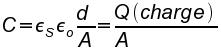
Capacitance is a measurement of the electrical charge stored in a device (held by an electric field) with a particular voltage potential.
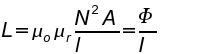
Inductance is a measurement of the magnetic field in a device with a particular current flowing through it.
Resistance is a measurement of the resistance to current flow.
Capacitance, inductance and resistance are physical properties of materials. Thus, the material has an implicit effect on a material's energy storage or dissipative abilities. This is exactly why electrical circuits are so susceptible to changes in environment. The material's C, L or R is effected by changes in temperature, applied voltage, applied frequency, physical dimensions, age, etc. So when analyzing a circuit I now consider the environment's effects on the C, L and R. In turn, I examine the effects of the change in C, L and R on the circuit's I, V and P.
| Resistor | Capacitor | Inductor |
| R=l*ρ/A | C=εs*εo*d/A=Q (charge)/A | L=μo*μr*N2*A/l=Φ/I |
 |
 |
 |
Energy & Power, Revisited, Part I
I'll skip some equations here (because for our discussion it doesn't matter), but if voltage is the potential for moving energy from one place to another and current is the rate and which it is displaced, then it must be possible to define the relationship between the two. It must also be possible to determine the amount of energy and power in a particular field (electric or magnetic).
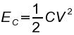
Now, we will set down some equations. This first set relate inductance (L), capacitance (C), and resistance (R) to energy and power. We'll see later that capacitors and inductors store energy and resistors only dissipate energy.
| Capacitor | Inductor | Resistor |
| EC=1/2*C*V2 | EL=1/2*L*I2 | ER=0 (pure resistance does not store energy) |
 |
 |
 |
Therefore, the energy in a device will depend on its capacitance and voltage (potential energy), inductance and current (kinetic energy) and the energy dissipated by a device will depend on its resistance. The capacitance, inductance and resistance can vary depending upon the environmental conditions.
Power is defined below:
P=V*I
The second set relate impedance (which is defined below) to voltage and current (and therefore energy and power). It is also a relation of potential energy to kinetic energy.
V=I*Z
So to recap: energy, work, power, properties of matter, potential and kinetic energy, and impedance.
Impedance
Impedance characterizes the relationship between current and voltage in a circuit. Impedance is a complex entity. The real portion represents the pure resistance (dissipative) of the circuit and the imaginary portion represents the reactance (storage) of the circuit. Pure resistance is DC (ƒ=0) relationship and reactance is a (AC) frequency dependent (ƒ>0) relationship. Together they represent the total relationship of current to voltage in a circuit. Ohm's Law defines this relationship.
V=I*Z
Using Ohm's Law we can relate the power and energy in a circuit to it's characteristic impedance.
P=I*V=I2*R=V2/R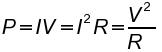
In a purely resistive circuit, power is dissipated. In a purely reactive circuit energy is stored or released, depending on the sign of the reactance. If positive, energy is being stored. If negative, energy is being released. Energy can only be dissipated by resistance and stored/released by reactance.
As you may already have figured out, inductance and capacitance is implicit in reactance and the relationship is direct.
| Capacitor | Inductor | Resistor |
| ZC=-j/ω*C | ZL=j*ω*L | ZR=R |
 |
 |
 |
where ω=2*π*ƒ.
Finally, the total impedance is defined as thus:
Z=ZR+ZL+ZC=R+j(ω*L-1/ω*C)=a+jb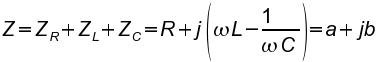
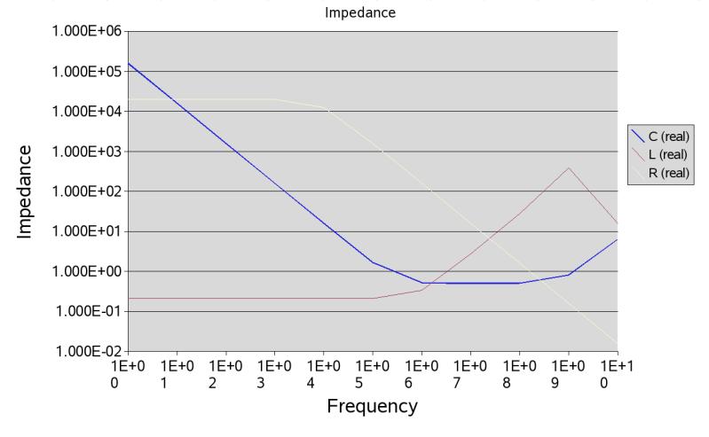
This impedance can be graphed from 0Hz to infinity. If you graph the resistance, it is always a flat line. If you graph the impedance of a pure capacitor, it starts from infinity, and falls off towards zero. The slope is determined by the capacitance. The higher the capacitance, the lower the impedance. Resonances are points of minimum impedance, or places where L and C cancel and the device becomes purely resistive. The sharpness of the resonances is defined as the "Q".
| Q |
| abs(X/R) |
 |
All materials and devices contain some resistance, capacitance and inductance, so there are three key things to take away here. The first is resistance is thought to be frequency independent, but it is not due to the skin effect. I know this seems obvious, but what this really means is no matter what frequency, there is some resistance. The second is that impedance is dominated by capacitive reactance at low frequencies. If the capacitance is small enough it will complete blot out the effects of resistance and inductance. At least to a point, which brings me to my third point. Inductance absolutely dominates impedances at higher frequencies. As frequency goes up capacitive reactance falls to zero and inductive reactance rises towards infinity.
Energy & Power, Revisited, Part II
Earlier we established that C and L effect the amount of energy in a device. We also established that impedance is a function of C, L and R. Now, because impedance has a complex relationship, any reactance in the circuit introduces phase into the circuit. Phase is simply a shifting in the alignment between current and voltage. Phase is important because it introduces is to the concept of negative power. For example, in a purely resistive circuit, the current and voltage are in phase. As a result power, P=V*I, is always a positive value. But, the current of an AC waveform where the current and voltage are out of sync, the current can be negative while the voltage is positive. Given P=V*I, the power at this point in time is negative.
What this really means is that in a purely reactive circuit it can absorb and release energy. Because all real devices have some inductance and reactance, they all have the potential to become sources or sinks (and can be both depending on the frequency). Conversely, this says that resistive circuits only disipate power.
We now turn out focus towards these real devices, what they look like, and how they behave.
Devices
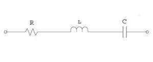
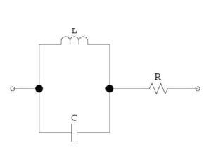
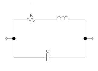
Devices in "real life" do not behave like ideally. Wires, traces, pads, vias and any current carrying apparatus do not behave ideally, with no stray resistance, inductance or capacitance. In reality all devices contain some amount of L, C and R. Very accurate models of components are quite complicated (they are circuits in themselves), but a good first approximation of real passives are displayed below.
| Real Capacitor | Real Inductor | Real Resistor |
| R-L-C | (L||C)-R | (R-L)||C |
 |
 |
 |
So from a certain point of view, there is no such thing as an inductor, capacitor or resistor. There are only devices that are "inductor-like", "capacitor-like" and "resistor-like". In other words, they have one characteristic (L, C or R) which tends to be dominant over the others.
When you graph the impedance of a typical capacitor, you end up with a 'V' shape. the '\' of the V represents the capacitive impedance dominating and the '/' represents the inductive impedance dominating. The point at which they meet is a resonance and is typically called the ESR, or equivalent series resistance. What this means is that after a certain frequency (the bigger the cap, the lower this resonance), the capacitor actually becomes an inductor!
Inductors are similar, but resemble mountains, or an upside down 'V'. The '/' of the mountain represents the inductive impedance and the '\' represents the capacitive impedance dominating.
Resistor plots tend to stay fairly flat, like you'd expect. The inductance has a pulling up effect and the capacitance has a pulling down effect, but they tend to cancel out fairly well. It does depend on the type of resistor, though. For example, a wirewound resistor has pretty high inductance.
What we see here is that all devices are really just filters. They store, release, or dissipate energy, but also filter. So when I'm analyzing a system, I look at its energy and filtering characteristics and how they affect the system overall.
Resistance acts as a tempering agent on resonance and Q. Remember that higher resistance lowers Q, or smoothes out an impedance curve.
- L-R: lowers resonant frequency
- C-R: increases resonant frequency
- L||R: increases resonant frequency
- C||R: decreases resonant frequency
Transient Response
Ideal resistors do not have a transient response. They operate perfectly linear in accordance with Ohm's Law. Circuits (or real resistors) with inductance and capacitance have a non linear behavior which manifests itself when current or voltage changes (usually the result of an impedance change) in the circuit and is typically called the transient response.
Let's look at the behavior of current and voltage in reactive circuits over time. τ is called the time constant. It is a ratio of how fast the voltage or current will change through a device. In other words, if you are using a capacitor as a voltage source, the current flow will be determined by the size of the resistance. A low resistance will quickly discharge a capacitor because it causes a large current flow. Think of this in terms of power dissipation. The capacitor has (potential) energy stored. What is the best way to dissipate it? The time constant is interesting because you can always predict how much a capacitor will be discharged at specific intervals (first time interval=63%, etc).
Inductors are similar, but you must think of an inductor as a current source . A larger resistance will cause a larger voltage drop and will more quickly dissipate the energy in an inductor.
| Capacitor | Inductor |
| τ=C*R | τ=L/R |
 |
 |
Capacitance will respond to a change in voltage with a current flow through the device. Inductance will respond to a change in current with a voltage drop across the device.
| Voltage | Current |
| V=L*di/dt=1/C ∫t-∞I*dt | I=C*dv/dt=1/L ∫t-∞V*dt |
When power is first applied to a capacitor, it has zero voltage drop across it and zero current flowing through it. This voltage source rises very fast and current flows through the device. As the capacitor reaches the same voltage as the source, it charges slower, the rate of change decreases to 0, and the current through the capacitor falls to zero. In real life the ESR of the cap will always cause some current to flow. In essence, the cap acts as a short at t=0 and becomes open at t=∞ (or close to it if you include the ESR).
When power is first applied to an inductor, it has zero voltage drop across it and zero current flowing through it. This voltage source rises very fast and current will flow in the inductor. The current through the device causes a voltage drop across the inductor. As the current through the inductor approaches the nominal source current, the rate of change of current decreases, and the voltage drop across the inductor falls to zero. In real life the ESR of the inductor will always cause some voltage drop across the device. In essence, the inductor acts as an open at t=0 and becomes a short at t=∞ (or close to it if you include the ESR).
As a result, it is important to consider both the steady-state and transient characteristics of the circuit and/or device (e.g. determining maximum voltage is a function of the maximum steady-state value plus its transient).
Extending this...
| di/dt=v/L+(dv/dt)*(1/R)+C*d2v/dt2 | dv/dt=i/C+(di/dt)*R+L*d2i/dt2 |
Conclusion
The relationship between capacitance, inductance and resistance is based directly on the intrinsic properties of the physical material. Every material has some dissipative (resistance) and storage (capacitive and inductive) characteristic. Impedance is the relationship between voltage and current and derives from the energy characteristic of the device. This relationship when plotted over frequency defines a filter. Therefore every device has both an energy characteristic and a filtering property. But, that model is only defined for steady-state. A complete analysis of voltage and current takes in to account both the steady-state and the transient characteristics of the circuit. Consideration for phase must also be made, and possibly whether or not the device is acting as a source or sink.
References
An excellent online tutorial: allaboutcircuits.com.
I also used Wikipedia for the following keywords: Energy, Work, Power, Inductance, Inductor, Capacitance, Capacitor, Resistance, Impedance, Current, Voltage, Power Factor.
- Log in to post comments